There is an interesting discussion in the SL Forum about a problem some people have had making Normal Maps for Second Life™. Jake Koronikov opened the thread. Jake had a problem with the normal maps creating a visible seam in the model.

For instance, the seam between the front and back sides of the avatar leg. Of you were making a manikin and using a normal map on it that seem would become visible as a step on the surface rather than the smooth surface it is supposed to be. You can see his images of the problem in the thread: Tangent spaced Normal Map seam visible in UV border area. (2017 – The images are gone.)
This is one of those problems that arise from misunderstanding how the Second Life™ system works. It seems the confusion is about what type normal maps Second Life uses. Plus there is the problem of which type of normal map the modeling program or the normal-map-generator in whatever program is being used.
So, what’s a normal map?
The SL Viewer looks at models in-world and figures out how light will bounce off them, reflects. If we make a shirt and model the buttons we see the raised buttons. The render engine shows the differences in lighting on the face and edges of the buttons. This takes a lot of polygons and the render engine has to do a lot of calculations.
Normal maps are a way to ‘pre-calculate’ the effect. We can use a flat surface and a normal map and the shirts will almost exactly the same. Thus the render engine has far less work to do.
So, normal maps are a way to represent 3D detail on flat surfaces that is way more efficient than building detail with polygons.
If you want more detail, see the Wikipedia: Normal Mapping.
If you want detail at computer programming levels see: Normal Mapping.
And the Problem?
The problem comes to the fact there is more than one way to represent that data the render engine needs to show the detail. Sort of an Android verses iPhone kind of thing. They do the same things in different ways.
Blender and Second Life use what is referred to as a +x +y tangent space normal map. The other kind is +x -y, which is what GIMP generates.
The problem comes when one has to flip their normal map to change it from -y to +y. The flip doesn’t work so well. The problem I suspect comes to the edges along the UV map islands no longer being a perfect match. Jake figured out one could extend the normal map out past the edge of the UV map islands and solve the problem. In printing terms, we would be adding ‘bleed’.
A better solution is to not have to flip the normal map. That is possible when the program you use to generate the normal map can be told which type of map to create. But, to create the right type of map you have to know about Normal Map Types. There are 3 basic types of maps:
- Tangent Space – This type references the surface it covers for left/right, forward/backward, and down/up directions. So, the normal map gives instructions to the render engine that a point on this surface should look like it is ‘this much’ farther right, forward, and above the surface.
- Object Space – This works the same except directions are given from the center of the model. This isn’t exactly right, but it is the idea. Directions are based on which way the model faces.
- World Space – Again this is similar, but the basis of directions is the world’s X, Y, Z coordinate system. Rotating a model in-world that uses this type of map will make the lighting look wrong.
In general, we use tangent maps for our normal maps in Second Life. They work for anything we might have in-world and we can move it and lights and the render engine makes it look as we intended. The problem is there are two types of tangent maps, the +y and –y. Second Life uses +y.
If you use the wrong type, the outie things look like innie things…
If you need to ‘flip’ or invert a normal map it is reasonably simple. In Photoshop select channels, pick the green channel and invert it (Ctrl-I). The problem Jake ran into is this is not always a perfect solution and MAY create a surface ridge along the edge of your UV Map islands.
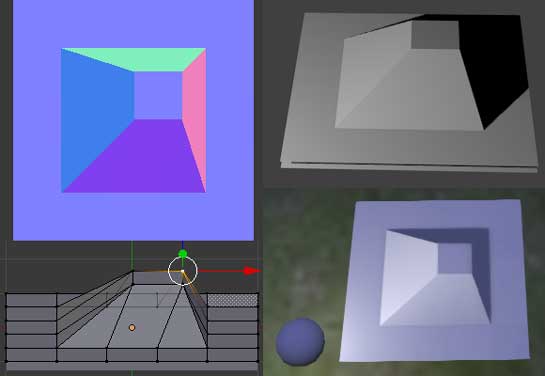
If you are looking at your normal map and wondering if it is right for Second Life because your program is no help, Drongle McMahon gives this simple advice: “…just try to remember that it has to look like red light from the right and green light from the top.” He provided an image to illustrate. The upper left image shows the idea.
Summary
If you are getting a ridge along the edges of UV Mapped areas when using a normal map, this is probably the reason.
It can also be possible that your UV map is upside down. Instead of looking at the outside of the surface you are looking at the inside. So, while you might have the correct normal map (+y) baking, it is being inverted by the UV layout. To correct that problem you rotate the problem part of the map 180 around either the X or Y axis, but never both. Think of turning a sheet of paper over.
I suppose it is simple enough to understand the problem, something is upside-down. However, clearly understanding which part is upside-down isn’t so easy. At least you’ll know what to look for.
Hi! Could you specify what you mean by rotating the “problem part”? //Jac
Like I said, think of the UV map being on a sheet of paper. Turn it over.